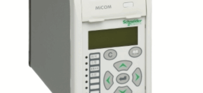
Using a Micrologic Relay in an ACB for Restricted Earth Fault (REF) Protection
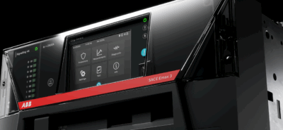
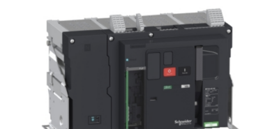
Modern ACB protection units such as Micrologic trip units from Schneider Electric allow REF-style protection using residual current measurement and external CT arrangements. While Micrologic isn’t a traditional standalone REF relay, it can be configured to provide zone-based earth fault protection when installed correctly.
🔧 What REF Protection Is Doing in This Application
Restricted Earth Fault protection is designed to:
✅ Detect internal earth faults inside a defined protection zone
✅ Ignore external earth faults downstream or upstream
✅ Provide fast trip times for safety and equipment protection
Typical zones include:
- Generator windings
- Transformer LV windings
- Busbar sections
- Incomer sections of LV boards
⚡ How Micrologic Achieves REF-Type Protection
Micrologic units typically use residual earth fault measurement, meaning:
The relay monitors:
Ia + Ib + Ic (+ In if present) = Residual Current
If the sum ≠ 0 → Earth leakage detected → Trip output operates.
To achieve REF-style protection (restricted zone protection), you normally:
1️⃣ Use External Core Balance CT (CBCT) or Residual CT Arrangement
Installed around:
- All phase conductors
- Neutral (if present)
This ensures only earth faults inside the protected zone are detected.
2️⃣ Wire CT Secondary Into Micrologic Earth Fault Input
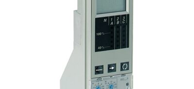
Depending on Micrologic version (P / H / X):
You configure:
- Earth fault pickup current (Ig)
- Earth fault delay time (Tg)
- Trip curve characteristics
For REF-style protection you normally use:
✔ Low pickup setting
✔ Fast or instantaneous operation
3️⃣ Define the Protection Zone Physically
The CT location defines the zone:
If CT is installed:
- After breaker → Protects downstream equipment only
- Before breaker → Protects busbar + breaker + connections
Correct positioning is critical.
🧠 Example REF-Type Application Using Micrologic
LV Incomer Protecting Transformer Secondary
Setup:
Transformer → CT Zone → ACB → LV Busbar
Micrologic monitors earth leakage only inside this zone.
If earth fault occurs inside:
✔ Trips instantly
If fault occurs downstream:
✔ Other protection clears fault
✔ ACB stays closed
🔋 Generator Application Example
Micrologic can be used when protecting:
- Generator LV output
- Generator breaker incomer
Using:
- CBCT around generator phase conductors
- Earth fault element configured low sensitivity
This provides early detection of winding insulation faults.
📊 Advantages of Using Micrologic for REF-Type Protection
✔ Integration
No separate REF relay needed in many LV systems.
✔ Cost Effective
Less panel space
Less wiring
Lower install cost
✔ Communication & Monitoring
Modern Micrologic allows:
- Event logging
- Fault recording
- Network comms
- BMS / SCADA integration
⚠️ Important Engineering Considerations
CT Matching
Incorrect CT ratios can cause:
❌ Nuisance tripping
❌ Protection failure
Stability During Through Faults
Must ensure CT saturation doesn’t create false residual current.
Neutral Considerations
If system has neutral:
Neutral must pass through CT window.
Earthing System Type Matters
Different approach for:
- TN-S
- TN-C-S
- IT systems
- Generator island mode
🏗️ Where This Is Commonly Used
✔ LV Incomers feeding critical busbars
✔ Generator incomer breakers
✔ Transformer LV secondary protection
✔ Data centres
✔ Industrial process plants
🛠️ How NKD-Type Integrators Typically Implement This
In real projects this usually involves:
- Selecting correct Micrologic variant
- Designing CT placement
- Setting earth fault pickup + delay
- Functional trip testing
- Injection testing
- Coordination with upstream HV protection
👍 When to Use Dedicated REF Relay Instead
Still recommended when:
- HV transformer differential schemes
- Generator primary protection
- High stability protection required
- Multiple CT schemes required